For manufacturers producing 6A–40A MCBs, coil winding involves much more than simply reaching the specified number of turns.
Wire feeding, front and rear lead bending, peeling position, coil dimensions, and unloading orientation all affect downstream welding and assembly. If these parameters are unstable, even a coil with the correct number of turns may not move smoothly into the next process.
From Wire to Finished Coil: How Does the Machine Work?
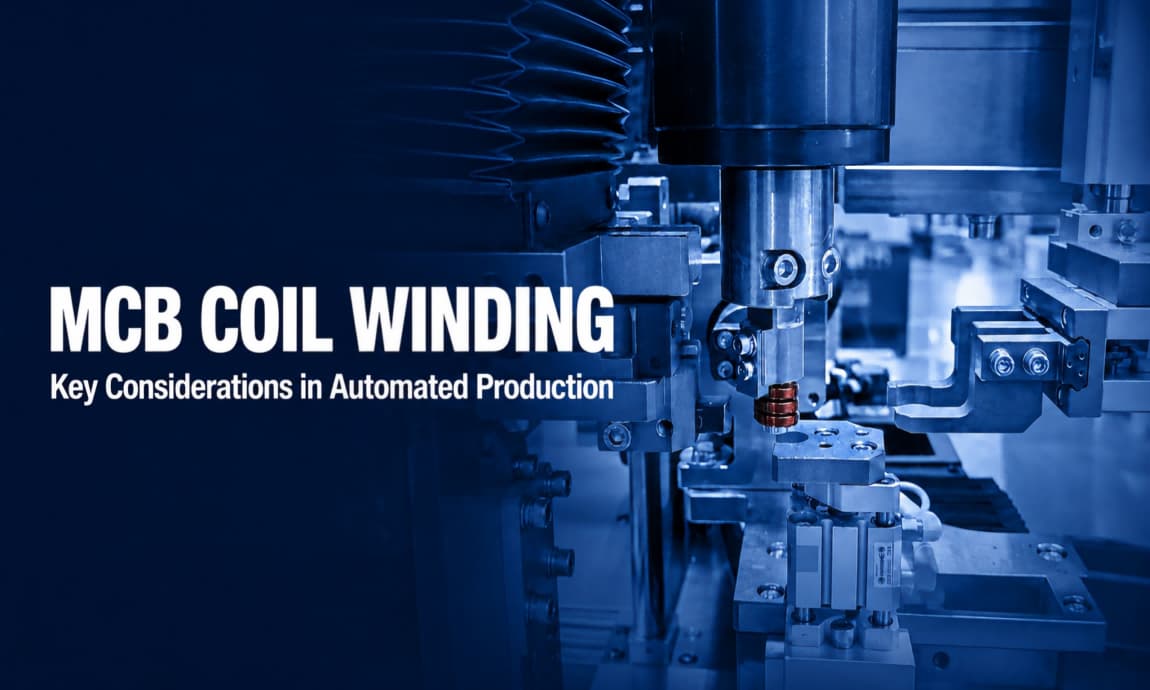
This automatic winding machine is designed for 6A–40A MCB coils and uses a multi-axis numerical control system to coordinate the different mechanisms.
The complete process includes:
Automatic wire feeding → Front lead bending → Wire positioning → Automatic winding → Wire peeling→ Cutting → Rear lead bending → Robotic pick-up → Finished coil unloading
After each production cycle, all mechanisms return automatically to their starting positions before processing the next coil.
Finished coils can be transferred to a collection point or placed into circulating fixtures in a controlled orientation for connection to downstream welding or assembly equipment.
Stable Wire Feeding Is the Starting Point for Winding Quality
As production continues, the diameter of the wire spool gradually decreases. This can change the unwinding resistance and the condition of the wire entering the machine.
Unstable wire feeding may cause:
Variations in lead length
Incorrect bending positions
Inconsistent coil dimensions
Loose or uneven winding
Changes in peeling and cutting positions
The wire-feeding mechanism must therefore remain synchronized with the bending, winding, and cutting operations.
Before designing the machine, the wire diameter, material, hardness, insulation and spool specifications must also be confirmed. The required tooling and process parameters cannot be determined from the MCB current rating or wire diameter alone.
The Correct Number of Turns Does Not Always Mean a Qualified Coil
In addition to controlling the number of turns, an automatic winding machine must also maintain:
Inner and outer coil dimensions
Winding direction
Winding tightness
Front and rear lead lengths
Lead bending angles
Peeling position and length
If the coil dimensions or lead positions are unstable, downstream automatic handling, positioning, and welding may still fail.
The winding tooling, wire guides, bending tools, and robotic grippers must be designed around the customer’s actual product. Before the final machine concept is confirmed, process trials should be carried out using the customer’s production wire and approved coil samples.
Why Do Peeling and Lead Bending Require Special Attention?
The front and rear leads normally need to be bent according to the product structure, with insulation removed from specified areas.
The stripping process must define:
Peeling position
Peeling length
Permitted insulation residue
Acceptable conductor damage
Effective contact area required for downstream welding
Insufficient peeling may leave insulation in the welding area. Excessive peeling or incorrect cutter positioning may damage the conductor.
The bending positions and angles of both leads must also match the fixtures used in the downstream welding and assembly processes.
How Is Changeover Managed Across 6A–40A Products?
Different MCB ratings may use different wire diameters, numbers of turns, and lead structures. Product changeover therefore involves more than changing the winding turns in the control program.
Depending on the product, changeover may involve:
Winding tools and mandrels
Wire guides
Bending tools
Peeling and cutting components
Positioning and clamping mechanisms
Robotic pick-up tooling
The machine adapts to different products through tooling changes, with a total target changeover time of within 30 minutes.
Wire-feeding length, winding turns, bending positions, and mechanism settings for each product can be stored and recalled automatically.
After every changeover, the operator must still verify the wire, tooling, product recipe, and first-piece quality before continuous production begins.
What Production Capacity Does a 2.5-Second Cycle Time Provide?
The machine can achieve a production cycle time of:
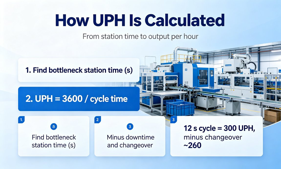
2.5 sec/pc
Based on this cycle time:
Theoretical capacity: 1,440 pcs/hour
Estimated capacity at 90% machine availability: approximately 1,296 pcs/hour
These figures are intended for preliminary capacity planning.
Actual output will also depend on the number of winding turns, wire characteristics, material replenishment time, changeover frequency, in-process inspection, maintenance, unplanned downtime, and the cycle times of upstream and downstream equipment.
When evaluating a machine, manufacturers should therefore verify not only the cycle time per piece but also its availability and yield during continuous production.
What Information Is Required Before Purchasing?
To evaluate machine compatibility, achievable cycle time, and final configuration, the customer should provide:
Coil drawings for each 6A–40A product
Samples of the actual production wire
Approved finished-coil samples
Target output for each product
Product changeover frequency
Coil quality and acceptance standards
Details of downstream welding or assembly processes
Available installation space and site conditions
Based on this information, the engineering team can confirm the winding tooling, stripping method, bending tools, pick-up mechanism, changeover concept, and inspection configuration.
Selecting an automatic MCB coil winding machine should not be based only on its fastest cycle time.
For multi-model production covering 6A–40A MCBs, the more important question is whether the equipment can consistently perform wire feeding, bending, winding, stripping, cutting, and unloading while maintaining stable coil dimensions, lead positions, and discharge orientation.
Only when wire validation, changeover design, quality control, continuous operation, and downstream integration are considered together can a cycle time of 2.5 seconds per piece be converted into reliable production capacity.