1. Production Challenges: Why Is Stable Welding Difficult?
In MCB fixed contact component production, the welding action itself is not necessarily the most difficult part. The real challenge is maintaining consistent component orientation, positioning and welding quality at a high production speed.
In a manual or semi-automatic process, operators are often responsible for terminal loading, contact orientation, positioning, welding and post weld inspection. As production volume increases, several problems may occur:
• Small terminals and contacts may overlap, reverse or jam during feeding.
• Different contact types may become mixed.
• Contacts with a defined welding face may be loaded incorrectly.
• Manual loading positions and operating speeds may vary.
• Contacts may be displaced, protruding or lifted after welding.
• Welding dust may affect fixture positioning and electrode contact.
• Defects may not be identified quickly when inspection relies on manual sampling.
• NG parts may enter the next assembly process.
If a machine automates only the welding action while feeding, identification, positioning, inspection and sorting still depend on operators, it is difficult to establish a stable continuous production process.
Fixed contact welding automation should therefore be designed around the complete process from the moment components enter the machine until the welded parts are inspected and discharged. When selecting Magnetic Components Welding Equipment, check whether its feeding, fixturing and inspection functions match the fixed-contact design used in the magnetic assembly.
2. Process Importance: Why Does Welding Affect Downstream Production?
The fixed contact is an important part of the MCB’s conductive and switching system. The connection between the contact and terminal directly affects component quality and subsequent assembly.
Three areas require particular attention.
Contact orientation
Fixed contacts may use different materials and structures.
Some silver-plated copper contacts can be welded from either face and do not require front-and-back sorting. Other contact types have a defined welding face and must be correctly oriented before entering the fixture.
If the welding face is positioned incorrectly, completing the welding cycle does not guarantee that the connection meets the process requirements.
Contact position
The terminal, contact and welding electrodes must maintain a stable relative position.
If the contact is displaced, not fully seated or moves during welding, it may be positioned outside the specified area, protrude from the terminal or remain lifted after welding.
These defects can affect both the fixed-contact component and the following assembly operations, resulting in additional rework or scrap.
Weld strength and appearance
After welding, the contact must maintain sufficient connection strength without visible scratches or deformation.
Electrode force, weld energy, component seating, electrode wear and fixture cleanliness can all influence the final result.
Weld quality should therefore not be judged only by whether the welding cycle has been completed. Position inspection, height measurement, weld-strength sampling and visual inspection should also be included in the quality-control process.
3. Which Key Problems Does This Machine Solve?
Automatic feeding and continuous operation
The terminals and fixed contacts are automatically sorted and transferred by vibratory bowl feeders and linear feeders. Material-shortage, part-arrival and feeding-jam detection are integrated into the feeding system.
A dual-track arrangement supports the parallel processing of two parts, helping the feeding capacity match the required machine cycle time.
This fixed-contact automatic welding machine has a buffer capacity of approximately 1,500 parts, supporting around 30 minutes of continuous production. If a longer unattended replenishment interval is required, an additional hopper can be included according to the production requirement.
Feeding stability still needs to be verified with actual components because dimensional tolerances, surface conditions and the tendency of parts to overlap can all affect feeding performance. For Magnetic Components Welding Equipment that handles these parts, feeding trials should use the actual production components.
Contact identification and orientation adjustment
A vision system identifies the contact type and its front-and-back orientation.
If the contact is incorrectly oriented, a pneumatic flipping or rotating mechanism adjusts it before loading. Components that cannot be identified, are incorrectly positioned or do not match the selected product type are prevented from entering the welding station.
The vision system does more than inspect the component. Its result is interlocked with pick-and-place handling, orientation adjustment, welding permission and alarm logic, reducing the risk of reversed contacts, mixed parts and incorrect welding.
Stable positioning and automatic welding
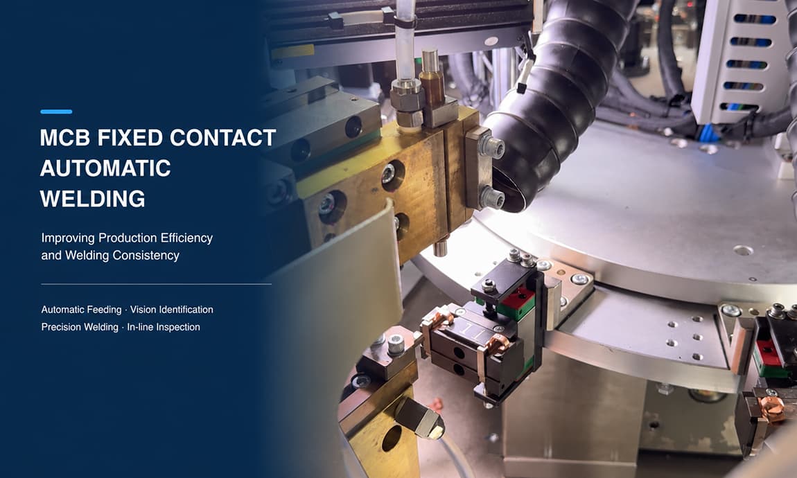
A pick-and-place mechanism automatically loads the terminal and contact into the rotary indexing fixture.
The dedicated fixture maintains the relative positions of the terminal, contact and electrodes, preventing component movement during welding.
A floating structure can compensate for small differences in component dimensions and loading conditions. However, the compensation range must be controlled to avoid reducing positioning accuracy.
The machine controls electrode force, welding time, weld energy and the dispensing amount of welding material. The final parameters are determined through welding trials using the actual production components.
The target cycle time of this fixed contact automatic welding machine is:
Two parts every 2.5 seconds—an average cycle time of no more than 1.25 seconds per part.
To achieve this target, the machine uses a multi station rotary indexing design. Feeding, contact identification, positioning, welding, in-line inspection, product sorting and fixture cleaning are performed simultaneously at different stations.
In-line inspection and NG separation
After welding, the vision system performs 100% inspection of the relative position between the fixed contact and the terminal. It checks whether the contact remains centred and whether any displacement or protrusion has occurred.
A displacement sensor then measures the contact height to detect lifting or incomplete seating.
The system automatically sorts the components according to the inspection results:
• Accepted parts enter the OK discharge channel.
• Rejected parts enter a separate NG channel.
• Inspection results remain associated with the corresponding fixture position.
• Repeated abnormalities trigger an alarm or machine stop.
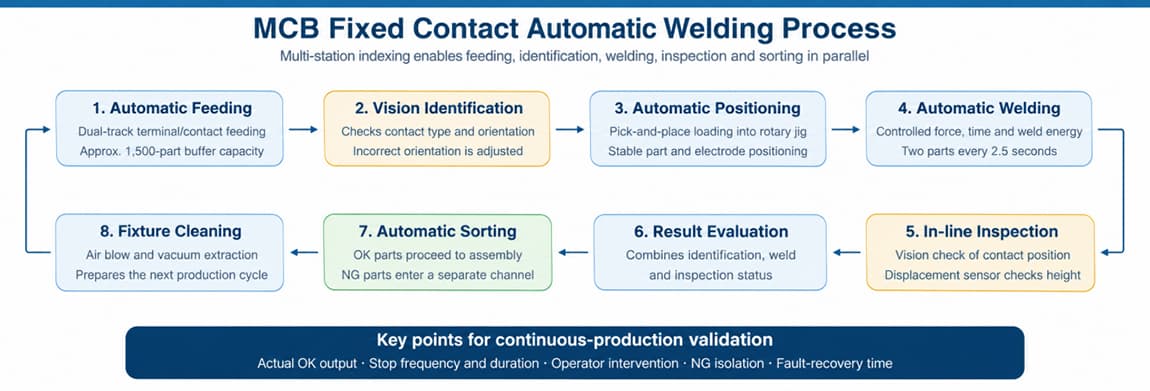
Weld strength and product appearance are verified separately through sampling according to the agreed quality requirements. In-line inspection and sampling cover different quality risks and cannot directly replace one another.
By integrating automatic feeding, vision identification, stable positioning, welding control, in-line inspection and NG separation, this machine turns an individual welding action into a stable continuous-production process. When this welding stage forms part of magnetic-component production, the same process checks apply when evaluating Magnetic Components Welding Equipment.