Last Monday's night shift pulled 210 MCB units off one welding station and set them aside. The thermal trip element on those units failed the pull test: the silver contact rivet lifted clean off the bimetal arm. On a thermal component welding equipment line, that is the signature of a cold weld, and it never shows up on the HMI until the reject bin does. Same station, same part number, a recipe that had run fine for months. The question was not whether the thermal component welding equipment had broken, but which variable had drifted while nobody was watching. We isolated the batch to a 90-minute window around the shift change. Before that window the cell had held a 0.4% defect rate; after it, rejects climbed to about 6%.
Two failure modes, two opposite causes
When we sort the rejects on a thermal component welding equipment cell, they split into two families that never look alike. The first is the cold weld we pulled that night: a dull, convex nugget that lifts in a peel test, contact resistance that reads fine cold and drifts after a temperature cycle. The second is burn-through: a dark crater with a ring of copper and silver splash, sometimes a pinhole through the bimetal, and an intermittent short downstream. One says the thermal component welding equipment station gave too little heat; the other says it gave too much. On a thermal component welding equipment cell, the cure for one is the opposite of the cure for the other, so chasing a cold weld by raising current when the tip is burned through only widens the defect. Figure 1 lays the two modes side by side with the causes we check first.

Where we look first
On each ACA Automation commissioning, the first suspect is never the recipe on the screen. It is the real value behind it. Secondary current drifts as SCR channels age and the secondary cable loosens; a weld checker, not the HMI number, tells you the truth. Electrode pressure sets the contact resistance, and low pressure on a thermal component welding equipment station gives splash and tiny nuggets, while high pressure squeezes the brazing layer out before it fuses. The copper-alloy tip mushrooms and picks up silver from the rivet face, the contact area grows, current density falls, and the next hundred welds go cold even though the setpoint never moved. We also flag the incoming lot: a thinner silver plating on a new rivet batch shifts contact resistance enough to turn an old recipe on a thermal component welding equipment line into a cold-weld recipe. When we audit a running cell, we log secondary current, tip force, and tip face diameter at the start of each shift. A thermal component welding equipment line that does not measure these three values cannot tell you why it made a bad batch until days later.
The parameter recovery order ACA Automation recommends
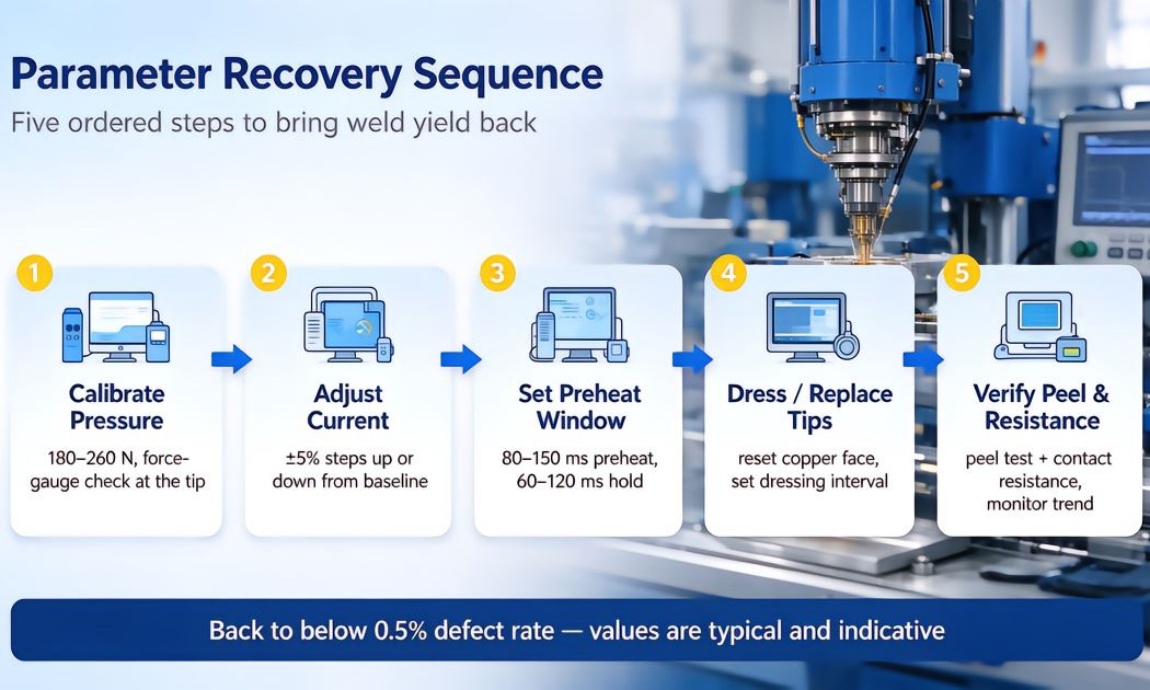
When a batch goes bad, change one variable at a time and run thirty pieces after each move. ACA Automation leads with pressure, because bad force makes the later adjustments guesswork: put a force gauge on the tip and fix the regulator until the fifty-cycle spread holds tight, roughly 180 to 260 N for MCB 6 to 32 A parts, typical and indicative. Then move the main weld current in ±5% steps from the known baseline. Next set the preheat window, 80 to 150 ms preheat followed by a 60 to 120 ms hold, lengthen it for cold joints and shorten it for burn-through. Dress or replace the tips and reset the dressing counter, then re-check plating on the incoming lot. This order is not a preference; it is how a thermal component welding equipment recipe stays reproducible across shifts, because pressure is mechanical and verifiable with a gauge, while current and preheat should move only after the mechanics are tight. When the numbers hold, the thermal component welding equipment cell deposits a stable nugget shot after shot. Figure 2 shows the sequence. An automatic welding equipment cell that can hold this window shot after shot is what our teams commission .
How to keep the failure from coming back
Thirty good pieces are not a result. Run a peel test at the start and end of each hour, trend contact resistance on an SPC chart, and write these checks into the acceptance run of any new thermal component welding equipment line. On that Monday batch, after pressure was re-calibrated, current was trimmed 5%, and preheat was extended 20 ms for the thin-plating lot, the reject rate fell from about 6% back under 0.5% within two hours. A well-built automatic welding equipment station exposes drift through current monitoring, force feedback, and shot counters instead of waiting for the bin to tell you. For a new thermal component welding equipment project, we build this monitoring into the machine from day one, so the thermal component welding equipment line reports drift before the reject bin does. If you are laying out MCB welding workcells, our automation solutions start from your part drawings. You can also review our thermal components welding equipment offering before the call.
Send ACA Automation your rejected samples and current recipe; our engineers will read the failure mode and tune the station with you.
FAQ
Why does a thermal component welding equipment station make cold welds one day and good joints the next?
Usually a drifted and mushroomed tip, a changed plating lot, or secondary current sitting a few percent off the HMI setpoint. Measure the real tip force and the real secondary current before you touch the recipe on the thermal component welding equipment line.
How do I tell a cold weld from burn-through without a microscope?
A cold weld is a dull, convex nugget that lifts in a peel test; burn-through is a dark crater with splash and a possible pinhole. Cold welds read fine cold and drift after thermal cycling; burn-through shows up as an intermittent short on the downstream test bench. Sorting rejects this way on a thermal component welding equipment line takes about ten minutes.
What starting window should I use for MCB thermal trip parts?
Tip force around 180 to 260 N, main current moved in ±5% steps, and a preheat of 80 to 150 ms followed by a 60 to 120 ms hold. Treat these as typical starting points and confirm the nugget size and peel strength on your actual bimetal and rivet lot before locking the recipe on the thermal component welding equipment cell.