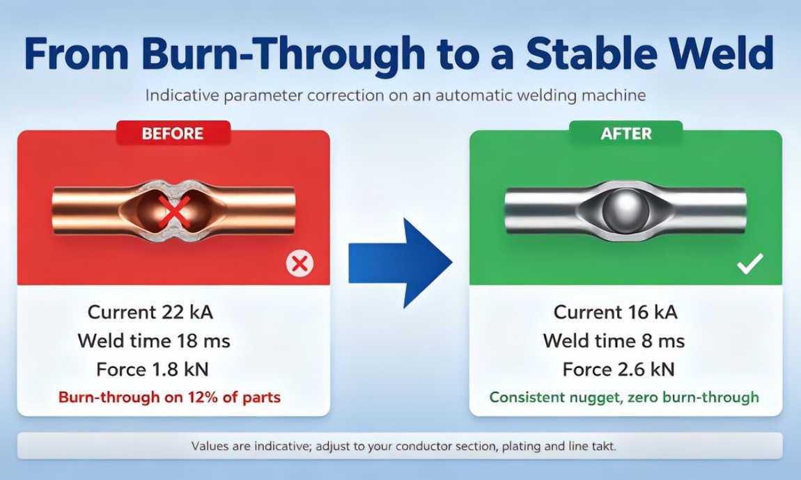
Split open the rejected MCCB conductor and the story is on the copper: a pinhole blown through the flexible braid where it meets the plated terminal insert, the edges melted and discoloured. The setpoint sheet taped beside the station read 22 kA, 18 ms, 1.8 kN. On this MCCB conductor welding equipment, the weld that morning had stopped being a weld and started being a hole. The first question on any MCCB conductor welding equipment line is not how fast you can cycle, but where the heat window sits for the conductor in front of you.
Burn-through on MCCB conductors means more heat went into a thin copper section than that section could carry away before current switched off. Give the joint too little heat and you get a cold weld that fails the pull test. Give it too much and the copper melts through before the hold cycle freezes the nugget. Takt pressure makes it worse: the faster the line runs, the less time heat has to leave between cycles, and the recipe that worked cold starts blowing through by the afternoon. That is the recurring failure mode on this MCCB conductor welding equipment line.
What the burn-through part was telling us
Look at the part, not the machine. MCCB conductors are usually electrolytic copper, and the section mismatch is the first clue. A thin braid welded onto a heavier rigid terminal is a two-section joint; the braid overheats first. A recipe tuned for the thick terminal will cook through the braid. On an MCCB conductor welding equipment cell, the thinnest section always melts first, so it sets the upper heat limit before the power supply does. Reading the conductor before touching the dials is the step operators skip and later regret on an MCCB conductor welding equipment cell.
Material and plating set the heat-input window
Plating moves contact resistance more than it moves bulk resistivity, and contact resistance is where the nugget lives. Silver plating gives low, stable contact resistance and the widest, most repeatable window on an MCCB conductor welding equipment recipe. Tin plating is soft and gives lower, more variable contact resistance, which invites expulsion on thin braids. Nickel plating keeps higher contact resistance, so heat concentrates at the surface and overheats the plating layer first. When the strip lot changes plating, do not copy the last recipe into the MCCB conductor welding equipment; the same 18 ms pulse that welded a silver part cleanly can burn through a tin one. Alloys matter too: brass or copper-alloy terminals carry higher resistance and want less current, not more. When the material certificate on the strip feed changes, the MCCB conductor welding equipment recipe has to change with it.
The current, time and force triangle
Resistance welding heat is I squared R t, and three dials on the MCCB conductor welding equipment move it: welding current, weld time, and electrode force. Raise current and heat climbs with the square of the value. Lengthen time and heat rises linearly, which lets it soak into the thin section. Raise force and you flatten the faces, lower contact resistance and push heat deeper; the window widens until you squash the braid flat. For a small MCCB copper joint, the indicative starting window on a DC inverter supply is roughly 8 to 20 kA, 4 to 16 ms, and 1.5 to 3.5 kN of force, typical numbers to be trimmed to your section and plating. The useful move is to lower current a little and shorten time together, cutting total heat without starving the nugget. A stable MCCB conductor welding equipment recipe reads as a short, flat pulse on the touchscreen, not a long over-driven one. Figure 1 shows that window and its two failure edges.
Takt versus cooling
Each pulse leaves heat in the conductor, the electrode tip and the fixture. At two to four seconds per part there is not enough time for it to escape, so the next weld starts on a warm part. ACA Automation treats this drift as the normal state of an MCCB conductor welding equipment cell, not a fault. Two levers fix it: pull heat out with water-cooled electrode holders and a small chiller, the single biggest lever on this MCCB conductor welding equipment, and give the joint time to cool with a deliberate dwell between batches. If production demands the fast cycle: derate the pulse, a little less current and a shorter hold, then re-check pull strength after 50, 100 and 200 cycles. On the MCCB conductor welding equipment HMI, watch tip temperature against the recipe; a steadily climbing tip means the cycle-1 recipe is no longer valid. Figure 2 shows the correction side by side.

How ACA Automation tunes a line
When ACA Automation commissions an automatic welding equipment cell for MCCB parts, the tuning order is fixed: start from the thinnest section, set force before current, then trim current and time together, and verify each step on inline testing equipment with a pull test or a sectioned cross-section. One recipe is locked per conductor section and plating, and re-baselined when the strip lot changes. Whether you build a dedicated MCCB conductor welding equipment cell or rework an existing press, that same tuning order holds. It is how a line stops fighting burn-through each shift and starts holding a stable window across a full production day.
Ask ACA Automation to review your welding line and send your part drawings for a feasibility study, rather than chasing cycle time on an MCCB conductor welding equipment that keeps melting through the same conductor.
Frequently asked questions
Why does burn-through start after hundreds of welds, not on the first parts?
It is thermal accumulation. Each pulse leaves residual heat in the conductor, electrode tip and fixture. Once the cell runs at a fast takt, there is not enough time between cycles for that heat to escape, so the next weld starts on a warm part. Water-cooled electrode holders and a controlled dwell bring the window back on the MCCB conductor welding equipment.
Does tin or silver plating on the copper conductor change the recipe?
Yes. Plating sets contact resistance at the faying surface. Silver plating is low and stable, giving a wider, repeatable window. Tin plating is soft and more variable, inviting expulsion on thin braids. Nickel plating keeps higher contact resistance, so heat concentrates at the surface. Re-tune the recipe whenever plating changes.
How do I run a fast takt without heat buildup?
Pull heat out actively and give the joint time to cool. Use water-cooled electrode holders, add a deliberate dwell, and if the cycle cannot move, derate the pulse with slightly lower current and a shorter hold. Re-check pull strength after the first 50, 100 and 200 cycles to confirm the window holds at running temperature on the MCCB conductor welding equipment.